
Saab b284 / A28NER highflow exhaustmanifolds
- Lammertse Techniek
- Oct 27, 2025
- 6 min read
Updated: Jan 4

First design of the manifold in plastic up to the latest version in stainless steel 316L.
The exhaust manifold of the V6 engine supplied in the Saab 9-3 from 2006 is a so-called “log” manifold. That means you have a straight tube on which the cylinder ports connect via smaller tubes. With the B284 and A28NER this has been designed such that after the exhaust gas leaves the exhaust port in the cylinder head it goes into the smaller tubes and then into the big “log” which sits perpendicular. That means there is very poor flow of exhaust gases. This causes the air to exit more poorly from the cylinder spaces, resulting in a lower filling degree.
This construction therefore results in the engine’s efficiency being lower than it could be. Because if the exhaust gases hit a wall then this creates back-pressure and heat. In addition it leads to uneven pulses arriving at the turbo and thus the turbo is not supplied cleanly in the ignition sequence of energy (hot exhaust gases). That causes heat and swirling which cannot be fully used for the turbo’s spooling.
In the process of improving our beloved V6 engine we therefore came up with the idea to develop a new and improved exhaust manifold with which we can increase the engine’s efficiency.
In this blog we will show the steps we have taken and will show the test results of the final exhaust manifold.
Mid-December 2025 we are expected to start taking orders for the manifolds.
The original manifold:

Step 1 is measuring the space in which the manifold must fit. We chose to scan the engine bay and a standalone engine. This allows us to place the design on the engine in the engine bay and take into account the dimensions.

Then it’s time to start with the first sketch. V1 was with a V-band clamp with the idea of quickly making a universal coupling so that anyone who buys a set of manifolds can easily have a set of uppipes made.
We had it 3D-printed:
This technique works fantastically and helps us to develop faster. The bed of the 3D-printer was not large enough to print a manifold in one piece, so it was printed in two parts.

To print the manifolds faster and better we purchased a 3D-printer with a larger bed. This makes it possible to make the manifolds and other prototypes in-house quickly. The result is unprecedented:

At Version 18 we felt very close to a first real stainless-steel prototype, so we began sketching uppipes that run from the manifolds to the turbo:

In this drawing we were able to draw the manifolds, uppipes and downpipe to see how everything should theoretically fit.
The uppipes are still in development but will likely follow based on assembly of the manifolds with handcrafted uppipes.
We printed and fitted V18:


It already looked quite like it, adjustments from here up to V21 were; plate thickness from 4 mm to 8 mm, different radii in the bends, thicker wall of the entire manifold 3 mm and EGT cut-outs.
Here is V21:


After printing that version we arrived at an even slightly modified and more streamlined version with mounting lugs for the original heat shields and without the EGT cut-outs. Otherwise the shields wouldn’t fit. The shields are important so that was not an option.
Then the last plastic print:


Here a picture compared the latest version versus the second last. if you look closely you can spot the differences

After fitting the last version we decided it was time to print in stainless steel 316L. With anticipation we waited, the result is so cool!

The flange still needed machining as expected. On average 0.30 mm needed to be removed, which is quite manageable. The next version will come with a flange thickness of 10 mm, then there remains enough material so it can be resurfaced a few more times and remain usable.


Photos from first version to last version:


Update 04-01-2026
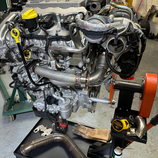
In December we were able to complete the exhaust manifolds together with the uppipes.
The uppipes have a slightly larger diameter than the outlets of the manifolds, allowing the hot exhaust gases to flow perfectly toward the turbo without any unwanted backpressure.
Just before the exhaust gases enter the turbo, a conical transition has been added to increase gas velocity, which in theory allows the turbo to spool up faster.
The exhaust manifolds and uppipes are connected using V-band clamps. These provide a strong and gas-tight connection while also allowing for quick assembly and disassembly.
This is what it looks like:


All welds are performed using backing gas. This ensures that the weld on the inside looks just as clean as it does on the outside.
Without backing gas, so-called “sugaring” or “cauliflower” formation can occur on the inside of the weld. These fragments can break off and damage the turbine wheel,something we definitely want to avoid.
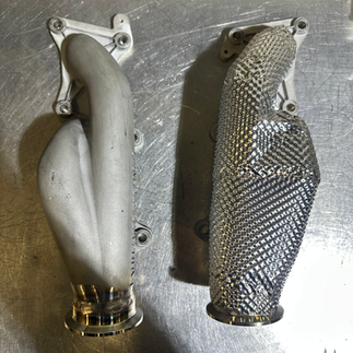
After finalizing the fitment of the uppipes and manifolds, it was time to insulate them. The goals of insulation are to reduce radiant heat as much as possible and to retain energy within the exhaust system, allowing more energy to reach the turbo.
These materials do a very good job: I have already measured a surface temperature reduction of around 50%. What effect this has at 2 cm or 10 cm distance is beyond what I can currently measure. Something for the future.
Dyno testing also showed that the turbo spools up earlier thanks to the combination of the new exhaust manifolds and insulation.


Assembled:


Next up was installation:

The sound, the first cold start (not truly ice cold, as the car was inside the garage).
What I immediately notice is that the exhaust pulses now sound fuller and more pronounced.
Now it’s time to hand the Saab Turbo X over to www.Dionhpt.nl, who will take the coming month to fine-tune the software on the original engine control unit.
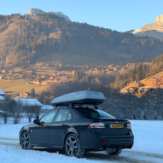
Just before the Christmas holidays, the idea came up to take the Turbo X on a ski trip to the French Alps. After consulting with Dion, we agreed this was feasible.
Before leaving, we quickly measured the power output and gave the Saab one final check for the long journey ahead.
The results are as follows:

Demonstrable Power Gains with Performance Exhaust Manifolds
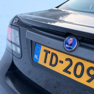
To objectively demonstrate the effectiveness of our performance exhaust manifolds, we conducted a direct comparison on a Saab 9-3 Turbo X equipped with a hybrid G25-660 turbo.
All measurements were carried out on the same dyno, using the same car, under identical conditions, and with optimized software to extract the maximum potential from both configurations.
The only hardware change between the tests was the exhaust manifold.
Results:
Stock exhaust manifold: 414.3 hp / 551.2 Nm
Performance exhaust manifold: 442.2 hp / 556.6 Nm
Power gain: +27.9 hp
Torque gain: +5.4 Nm, intentionally limited as we aim to retain the original character while simply providing more immediately available power
Additional software tests showed torque figures as high as 614 Nm
More important than peak numbers is the difference in power delivery. With the performance manifolds, power continues to build noticeably longer, while the stock manifold begins to restrict flow at higher RPM.
These gains are the direct result of:
Optimized exhaust gas flow
Lower exhaust manifold pressure before the turbo (EMAP)
More efficient use of turbine energy
In real-world driving, this translates to an engine that breathes more freely, pulls harder at higher RPM, and makes better use of the available turbo pressure.
Our performance exhaust manifolds therefore don’t just deliver higher peak power, but approximately 7–8% more usable power across the entire RPM range (AUC, area under the curve).
The result is an engine that breathes easier, pulls longer, and feels noticeably faster in everyday driving.
This excellent software setup has been developed to achieve the best possible power delivery using the original engine control unit. That said, we are currently reaching the maximum airflow that the MAF (mass air flow sensor) can measure.
This means there is still more power to be unlocked once we develop a solution for this limitation. Plenty of challenges ahead for 2026!
After these fantastic results, it was time to take the Saab on holiday. I captured some photos and videos in the French Alps that I’m happy to share with you.


We also managed to shoot some video footage and turned it into a reel.
All in all, the driving experience is fantastic: power is always available and perfectly controllable with your right foot. In our opinion, this is how the Turbo X should have left the factory.
Interested in the exhaust manifolds? You can order them here:

Very interested in this for my 2015 Holden insignia vxr. Waiting to see the uppipes. Most probably worth the shipping to Australia!!!
Your incredible projects provide verification that Saabs are engineered for all drivers and you prove daily driving of Saabs is what they were intended to be used for, not only on sunny days (Remember that new ones aren't being manufactured). It's a sports car with limitations still being researched. I look forward to reading your research and project updates from the Northeast USA. Saab, still generating smiles and looking forward to the curves ahead.
This is an amazing project, your ideas and assumptions seems very logical and follow a straight line to allow better air flow in a well known “bottle neck “.
I have had the opportunity to visit you and your shop and see the project and your attention to details is second to none. It will be a true pleasure working with you on a new project.